RTD Sensors including Pt100 and Pt1000 Elements (PRT)
In our RTD Sensor technical reference section you will find resource material covering all aspects of RTDs, from basic theory, product selection to accuracy, resistance and output reference charts.
If you have a question that isn't answered here, why not ask us via the contact form or call us.
Table of contents
1. Why is temperature measurement important?
2. What is a Resistance Temperature Detector?
6. What Different Types of RTD are available?
8. RTD vs Thermistor Comparison Video
9. RTD vs Thermocouple Comparison Video
10a. Benefits of Mineral Insulated RTDs
10b. Bend Radius of Mineral Insulated RTDs
12. Temperature Vs Resistance for Pt100 Sensors (Pt100 Resistance table)
13. Temperature Vs Resistance for Pt1000 Sensors (Pt1000 Resistance table)
14d. Immersion and Stem Conduction Errors
14f. Long Term Stability and Repeatability
1. Why is temperature measurement important?
Temperature is often a critical factor in manufacturing and is one of the most widely measured variables in industrial processing.
It is used for combustion, drying, refrigeration, calcination, heat treatment, calibration, material testing and extrusion amongst others in a variety of industries including Oil & Gas, Power, Refining, Petrochemical, Pharmaceutical, Food Production and more.
Even a small measurement error can be disruptive and often very costly in some processes. As well as this, keeping a process at optimum temperatures can lead to higher profitability.
Resistance Temperature Detectors (RTD) are considered to be amongst the most accurate temperature sensors available. In addition to offering very good accuracy, they provide excellent stability, repeatability and have a high immunity to electrical noise. This means RTD Sensors are well suited for applications in process and industrial automation environments, especially around motors, generators and other high voltage equipment.
There are many things to consider when selecting resistance temperature detectors for an application, as we will see below.
2. What is a Resistance Temperature Detector?
A Resistance Temperature Detector (RTD) is a temperature sensor which contains a resistor, the resistance changes with temperature; this can then be correlated to provide a temperature reading.
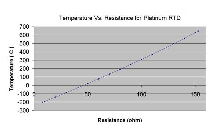
Detectors are most commonly made using platinum (Pt) because it follows a very linear resistance-temperature relationship in a repeatable manner over a large temperature range.
They are also know as Platinum Resistance Thermometers (PRT). PRT sensors can be flat film for low temperature applications or wire wound for higher temperature applications.
The RTD Pt100 sensor is the most common and has a resistance of 100 ohms at 0°C whilst the Pt1000 sensor has a resistance of 1000 ohms as 0°C. As Pt1000s have a higher resolution they are considered to be more accurate, this is because sensitivity or uncertainty is reduced in basic 2-wire sensors, however this uncertainty can be further reduced by using 3 or 4 wire RTD sensors (see RTD Circuits below).
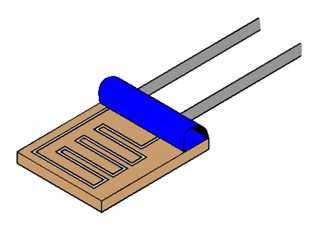
3. Flat Film Detectors
Flat film detectors are manufactured by placing a fine layer of platinum wire onto a ceramic substrate. The element is then coated in epoxy or glass which provides protection. They are a cheaper alternative to wire wound detectors and have a fast response time, however they offer less stability and have a lower temperature range than their wire wound counterparts.
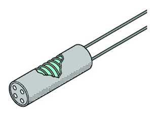
4. Wire Wound Detectors
Wire wound detectors consist of a length of fine coiled platinum wire wrapped around a ceramic or glass core. They are relatively fragile and are often supplied with a sheath for protection. They have greater accuracy over a wider temperature range than flat film detectors, however they are more expensive.
5. RTD Circuits
An RTD sensor consists of more than just an element; the element is just part of a circuit that is made up of at least two and up to four lead wires, with any number of connectors and accessories. The circuit configuration can be dependent on a number of factors. Including:
• Distance between the sensing area and the instrumentation
• Temperature in the sensing environment across the length of the sensor
• Connection preferences
• Current wiring configuration e.g. a 4 wire sensor won't be compatible with a 3 wire configuration
2-wire RTDs are the least accurate of the three circuit types as there is no way of calculating or eliminating the lead wire resistance between the detector and the reading. This creates uncertainty in the reading, so these sensors are often only used with short lead wires where accuracy is not of great importance. 2-wire Pt1000s can be used to reduce sensitivity and uncertainty but still don’t provide a true accurate reading.
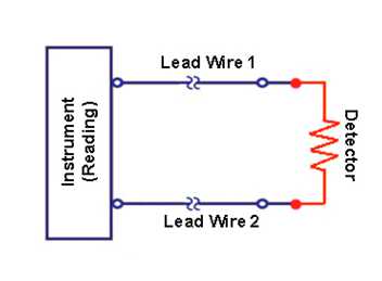
3-wire RTDs are the most commonly used RTD sensors. Assuming all three lead wires are the same the third lead wire calculates the average lead wire resistance throughout the circuit and removes it from the sensor measurement. This makes 3-wire RTDs more accurate than their 2-wire counterparts but less accurate than 4-wire configurations, however in circuits with long lead wires where there are long distances between the detector and the reading, significant savings can be made by using a 3-wire construction.

4-wire RTDs are used in applications where close accuracy is paramount. In a 4-wire RTD the actual resistance in each of the lead wires can be measured and eliminated leaving the exact resistance of the detector. The 4-wire circuit works by using the first two lead wires to power the circuit whilst the 3rd and 4th wires read the resistance in each lead wire compensating for any differences in lead wire resistance.

6. What Different Types of RTDs are available?
Sterling Sensors manufacture Platinum RTD sensors (also known as PRT sensors) in accordance with IEC751 to Class A, B, 1/3 DIN, 1/5 DIN and 1/10 DIN. RTD probes can be supplied in Pt100, Pt500 & Pt1000 as a bare element only, fabricated construction and up to a more complex mineral insulated assembly with single or duplex elements. Whatever your needs, Sterling Sensors will be able to supply a product for your application.
Available in wire types and lengths to suit your needs, we manufacture a range of bare wire resistance thermometers in Pt100 and Pt1000 for temperature measurement applications such as test and measurement, temperature mapping and OEM applications. If you are looking for a low cost general purpose sensor with fast response, wire RTD sensors are an ideal starting point.
This range of resistance thermometers commonly uses a fabricated sheath to protect the RTD element. They are available with your choice of detector from Pt100 to Pt1000 and precision options with a wide range of terminations, such as lead wires and plugs. Fabricated RTDs are also available with various types of Industrial head assemblies and safe area transmitters for an extensive range of applications.
Whether you require temporary or permanent surface measurement, we have a wide selection of surface RTDs available for use on many surfaces and applications including Research and Development, pipes and ducts.
Our general purpose resistance thermometers include bayonet sensors for the plastics industry, load probes for Pharmaceutical and Autoclave applications, as well as oil seal probes for bearing housing temperature measurement. There are even options for internal and external ambient temperature measurement. This range also features RTD's with a "Lemo connector" termination, a universal connector widely recognised in industry, designed for high accuracy and very fast interchange of sensors. (We also supply matching Lemo sockets)
Mineral Insulated RTD probes are robust and can be shaped and formed to suit any application without affecting the sensor. These sensors are available in long lengths and with a broad range of diameters. They can be used at higher temperatures than fabricated RTD’s and have a better accuracy, repeatability and long term stability than Mineral Insulated Thermocouples.
7. 7 easy steps to choosing an RTD
When selecting the right Platinum Resistance Thermometers (also known as RTDs, Pt100 rtd & rtd probe), there are many things that need to be considered.
Customers often come to us with a drawing, specification, photo or just an idea of what they want and we generally take it from there.
By asking a few questions we can normally work out what RTD sensor you want. However, in many cases our customers are left to source items with minimal information provided to them from a third party customer or engineer within the organisation.
Alternatively, you may simply have a new application which needs temperature measurement and have never purchased this type of product. Again, we are able to help.
Below we discuss the 7 steps you need to consider in order to get the right RTD sensor for your application.
1. Element Type
Do you know the RTD element type you need? Such as Pt100 or Pt1000. If not, this is the first thing you need to consider. Whatever you are connecting the RTD sensor to normally determines this.
2. Application
What is being measured? Is the rtd probe measuring a liquid, surface or a gas? Does it have to sit in a pipe or a vessel or is it part of a machine or apparatus?
3. Environment
What considerations need to be thought about? E.g. Does it need to be chemically resistant, IP rated, ATEX approved, food use, high vibration?
4. Location
How is the RTD fixed to the application, such as; wall mounted, hand held, outside or inside. Does it need a fitting to be held in place?
5. Operating Range
(E.g. 0 – 1000 Deg C) This is the main limiting factor when choosing RTD sensors as it determines the materials used in the construction.
6. Physical Considerations
What are the length, diameter and size requirements? Does is need to be bent or extremely long?
7. Connection to Application
What is the RTD being connected to? Does it need a terminal head, connector, wire or transmitter? You also need to understand if you need 2 wire, 3 wire or 4 wire configuration.
If you can answer these questions, then you should be able to determine the RTD you want. To help you, we have an easy to use questionnaire which can be completed and returned to us, or you can simply call or email us with your questions, we are here to help.
8. RTDs vs Thermocouples comparison video
A practical guide to help you choose the right product for your application.
9. RTDs vs Thermistor comparison video
A practical guide to help you choose the right product for your application.
10a. Benefits of Mineral Insulated RTD Sensors
Rapid response
The high density of the mineral powder promotes rapid heat transfer between conductor and sheath.
Highly flexible
Mineral insulated cable is highly flexible and can be formed in to angles and shapes to ensure a perfect fit in the application. This also allows easy installation in locations where access is difficult.
Wide temperature range
Mineral insulated sensors are a popular choice as they have a very wide temperature range. Fire-proof and can be exposed to considerably higher temperatures than synthetic sheath cables.
Long life
The construction of the cable guarantees a long conductor life, due to the sheath and insulating powder protecting them they are able to withstand environmental conditions such as corrosion.
10b. Minimum Bend Radius of Mineral Insulated RTDs
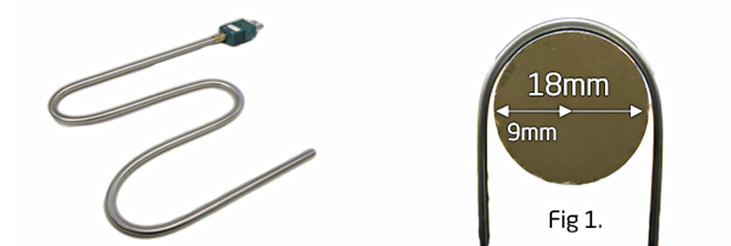
Mineral Insulated Thermocouples can be bent in to many elaborate shapes. However, there is a minimum bend radius, which is 3 times the cable diameter.
The above image shows a 3mm diameter MI cable at its minimum bend. To calculate the minimum bend radius you simply multiply the diameter of the cable by 3, therefore the minimum inside radius of a bend for 3mm cable must be 3 x 3 = 9mm.
To calculate the circumference (18mm in fig 1) simply multiply the radius (9mm in fig 1) by 2. This is the minimum size of former you would have to use to form your MI cable in to shape.
11. Questionnaire for selecting RTD Sensors

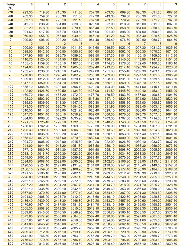
12. Temperature vs. Resistance for Pt100 Sensors (Pt100 Resistance table)
The table below can be used as a referencing tool to find the relationship between a range of temperatures and resistance for Pt100 RTD sensors. Temperatures in multiples of ten can be found down the left axis, whilst for more precise readings you must move along the horizontal axis between one and nine. For example the resistance of a Pt100 at 126°C is 148.32 Ohms.

For Pt1000 resistance v temperature characteristic, please use the Pt100 chart above and simply multiply the resistance by 10
13. Temperature vs. Resistance for Pt1000 Sensors (Pt1000 Resistance table)
The table below can be used as a referencing tool to find the relationship between a range of temperatures and resistance for Pt1000 RTD sensors. Temperatures in multiples of ten can be found down the left axis, whilst for more precise readings you must move along the horizontal axis between one and nine. For example the resistance of a Pt1000 at 126°C is 1483.30 Ohms.
14. RTD Accuracy
14a. Tolerance
IEC 60751:2008 is considered the international standard and specifies the tolerances for platinum RTD elements. The two most common tolerances for Pt100 RTD sensors are class A and Class B, for closer tolerance 1/3 DIN and 1/10 DIN standards are available. The higher the element tolerance the broader it’s range to deviate away from the temperature-resistance curve increasing the level of uncertainty, although strictly speaking this doesn’t make 1/10th DIN detectors any more accurate then class B detectors, however it does significantly reduce uncertainty of reading. The table below shows the tolerance for class A and class B detectors as defined by DIN 43760, these standards are then used to find the tolerance of 1/3 DIN and 1/10 DIN detectors. As you can see the tolerance of a class B detector is ten times higher than the tolerance of a 1/10 DIN detector meaning the uncertainty of reading in a class B detector is ten times higher than in a 1/10 DIN detector. It should be noted that tolerances defined in the table below only refer to bare detectors and do not account for the design or construction of the complete sensor.

Misinterpretation of tolerance can lead to unnecessary expenditure as people assume closer tolerance assures better accuracy.
Where the differences in uncertainty can be eliminated or significantly reduced a calibrated class B detector is more cost effective than 1/10 DIN detector for example if an RTD feeds into a process control system the characteristics of each individual sensor can be input eliminating the uncertainties identified in calibration.
14b. Uncertainty
There are three major uncertainties to consider when trying to define RTD accuracy:
• Detector tolerance
• Uncertainty due to sensor construction
• Uncertainty in calibration procedure
Points two and three are difficult to predict precisely as considerations for self-heating and stem conduction must be made.
14c. Self-Heating Effect
When electrical energy is applied to a resistor it generates thermal energy which in turn radiates heat creating uncertainty, this is known as the self-heating effect.
At high temperatures it has little effect on temperature and thus temperature measurement, however at low temperatures or where accurate measurement is required heat generated by self-heating must be taken into account and eliminated. It is possible to reduce self-heating by reducing the measurement current to the detector.
14d. Immersion and Stem Conduction Errors
Where RTD sensors are only partially immersed in a measured variable, stem conduction can occur. Typically your minimum immersion depth should be no less than four times the length of the detector or sensing junction.
If the immersion depth is less, stem conduction errors will occur, this is the effect of heat transfer into or away from the variable being measured via the stem or sheath for example if the sensors sheath is hotter at ambient temperature than the variable being measured heat will be transferred to the variable creating uncertainty of reading.
Stem conduction effect can be reduced by increasing the immersion length, reducing the wall thickness of the sheath or changing the sheath material.
Stem conduction errors most commonly occur under laboratory conditions; however it must be noted that they can cause significant errors in other industries.
As a rule of thumb, RTDs should be immersed 4 times the element length. (Flat film elements are typically 2-3mm, whilst wire wound elements are approximately 15mm or more) Read more about elements here.

14e. Measurement Current
It is widely recognised that in the majority of applications Pt100 sensors should have a measurement current of 1mA, however to reduce the effects of self-heating in low temperature applications where accuracy is paramount 0.5mA should be used.
Certain applications do require a higher measurement current and many detectors are frequently used at 10mA with little effect on performance and service life.
14f. Long Term Stability and Repeatability
RTD sensors are renowned for having excellent stability and repeatability; however sensor construction, the measurement environment and extremes of temperature can affect long term stability.
As a guide it is estimated that in the vast majority of applications an RTD sensor should experience no more than ±0.02 °C of drift per year assuming temperatures up to 450 °C without extremes of vibration or mistreatment.
Repeatability should only be affected if the same thermal conditions cannot be achieved or if identical RTDs have variations in construction.
For more information on Platinum Resistance Thermometers take a look here:-
National Physics Laboratory - What is a Platinum Resistance Thermometer?
Wikipedia - All about Resistance Temperature Detectors
Temperatures - Resistance Temperature Detectors
15. Summary
As you can see there is a lot to consider when choosing the right RTD sensor for your application. This page should provide you with the information you need on detectors, circuits, sensor accuracy and the different types of platinum RTD's.
If you would like to discuss your application further or to place an order please call +44 (0)161 620 0410 or Email sales@sterlingsensors.co.uk.
If you are unsure which RTD Probe you require drop us an email or give us a call and our friendly sales team will guide you every step of the way.
View our RTD range

 Made in the UK


